What is an MV cable termination, and what types are there?
An MV cable termination is the accessory that controls the electric field at the end of an XLPE-insulated medium-voltage (MV) cable and protects the insulation from the environment where the cable connects to switchgear, a transformer or an overhead line; a cable joint splices two cable lengths while maintaining insulation and screen continuity. Where the cable's semiconductive insulation screen ends, the field lines crowd together, and the main job of a termination is to spread that stress with stress-control elements. A termination is therefore not a simple insulating sleeve but the most electrically sensitive part of the entire cable system.
The most common types on site are heat-shrink, cold-shrink and premolded push-on terminations. Indoor and outdoor versions are distinguished by application; outdoor terminations carry sheds that lengthen the surface creepage path. In compact switchgear and transformer connections, screened T-type separable connectors (plug-in terminations) that mate with the equipment's bushing interface are widely used.
Joints use similar technologies. When selecting accessories, the cable cross-section, conductor material (copper or aluminum), insulation diameter range and voltage class must all be verified together. Type testing of accessories is defined by standards such as IEC 60502-4 and HD 629.1, but what really determines performance in the field is installing the product strictly in line with the manufacturer's installation instructions.
What are the most common MV cable termination installation mistakes?
The most common mistakes are an uneven cut of the semiconductive screen, knife scoring on the insulation, stripping dimensions that deviate from the installation instructions, and incorrect cleaning. Burrs left on the semiconductive cut edge, carbon traces on the insulation surface, or a stress-control element positioned incorrectly relative to the cut edge all concentrate the electric field at exactly the point that most needs protection.
Cleaning is a discipline in its own right: the insulation surface should be wiped with a manufacturer-approved cleaner in one direction only, from the insulation toward the semiconductive screen. Wiping the other way drags conductive particles onto the insulation, and dust, moisture and skin oils have a similar effect. Installing in rain or dusty conditions without a protective tent significantly increases this risk.
On the mechanical side, the usual culprits are lugs crimped with the wrong die, connectors that have not been deburred, air voids caused by uneven heating of heat-shrink material, and poorly grounded screen wires. With T-type connectors, typical mistakes include too little grease on the bushing interface, a connector that is not fully seated, and bolt torque that is never checked. Bending the cable below its minimum bending radius or leaving its weight hanging on the termination also stresses the interface over the long term.
Why do termination defects turn into failures months later?
Failures appear months later because most installation defects do not break down at first energization; instead, they trigger a slow degradation process that starts with partial discharge and ends in insulation breakdown. The field concentrated at the defect produces micro-discharges in small air voids or contaminated interfaces on every voltage cycle. These discharges erode the insulation step by step and eventually create electrical treeing or surface tracking.
Depending on defect severity, operating voltage, thermal cycling and humidity, this process can take weeks, months or even years. Moisture that enters a termination or joint accelerates insulation degradation, while a loose lug connection heats up and thermally ages the surrounding insulation. The outcome is usually the same: an unexpected phase-to-ground fault, damage on the switchgear or transformer side, and an unplanned outage.
The chain can be summarized as installation defect, local field concentration, partial discharge, insulation erosion and, finally, breakdown. A circuit that appears to run without problems after energization therefore does not prove the termination is sound; until the defect is found by testing, it stays in the system, waiting.
Which tests should be performed before a newly installed MV cable is energized?
The core pre-commissioning test set for a new MV cable circuit is a visual and documentation check, phasing and continuity checks, insulation resistance measurement, an outer sheath (jacket) test and a VLF withstand test. Where possible, this set is supplemented with tan delta and partial discharge measurements, and insulation resistance is measured again after the withstand test. Before testing, equipment that is not rated for the test voltage, such as voltage transformers and surge arresters, must be disconnected, and the cable-end connection arrangement must follow the switchgear and accessory manufacturers' instructions.
In common practice, VLF testing is performed at 0.1 Hz, while test voltage and duration depend on the approach adopted. The IEC 60502-2 and HD 620 approach uses 3U0 for at least 15 minutes, whereas the IEEE 400.2 approach uses tabulated values by voltage class and 30 to 60 minutes; which approach applies must be defined in the contract in advance. Here U0 is the cable's rated phase-to-ground voltage: under the 3U0 approach, a 12/20 kV cable has a U0 of 12 kV, so the test voltage is 36 kV rms. Durations between 15 and 60 minutes are typical for new installations, and the value should be stated explicitly in the owner's specification.
High-voltage DC testing of XLPE cables is no longer recommended by IEEE 400 or by most manufacturers. IEC 60502-2 still lists a 4U0 / 15-minute DC option for newly installed cables, but it should not be used on cables already in service and should only be considered with the caveat that it may harm the insulation. DC voltage can cause space-charge buildup in XLPE insulation, may fail to reveal some defects that would cause problems under AC operation and, particularly in cables aged in service, can trigger a failure after re-energization. Tests must be performed with instruments in valid calibration, and voltage, duration, measured values and ambient conditions must be recorded for each phase.
How do VLF, tan delta and partial discharge tests differ?
A VLF withstand test gives a pass/fail result, tan delta measurement shows the overall condition of the insulation and the effect of moisture, and partial discharge measurement reveals whether a defect exists and where it is. The three are complementary, not alternatives. Relying on a withstand test alone can leave hidden the defects that do not break down within the test period but will grow in service.
Tan delta (dielectric dissipation factor) is usually measured in steps such as 0.5U0, U0 and 1.5U0. Three indicators are evaluated: the stability of the value during the measurement, the increase in value as voltage rises (tip-up), and the absolute level. Guides such as IEEE 400.2 classify results as "no action required," "further study advised" and "action required"; the real benefit, however, is being able to track the trend of the same circuit over the years.
In partial discharge (PD) measurement, discharge magnitude is recorded in picocoulombs (pC) together with the inception and extinction voltages; the measurement principles are defined in IEC 60270. Time-domain reflectometry (TDR) pinpoints the distance along the cable from which the discharge originates, showing whether the source is a termination, a joint or the cable body. No meaningful partial discharge is expected at test voltages in a correctly installed new XLPE system, so discharge located at a termination usually points to an installation defect.
What happens if an MV cable test fails?
If a test fails, the circuit is not energized: the fault is located, the root cause is identified, the defective section is redone and the entire circuit is retested. If breakdown occurred during VLF testing, the fault is first prelocated using TDR and a surge generator (thumper), then pinpointed on site with acoustic or electromagnetic methods. If partial discharge has been localized to a termination, that termination is removed and reinstalled with a new accessory.
High or unstable tan delta values do not in themselves mean breakdown, but they suggest moisture ingress at cable ends or joints, or contamination at an accessory interface, and they call for further investigation. At this stage, surface inspection of the removed termination, photo-documented installation records and accessory batch numbers make the root cause much easier to understand.
Post-repair testing must cover the entire circuit, not just the repaired point. An "energize it once and see" approach risks the failure occurring inside the switchgear or transformer, at a far more expensive point. The provisional acceptance certificate should not be signed until the acceptance criteria are met.
What qualifications should you look for in a cable termination and testing team?
The essential qualifications are a crew trained by the manufacturer of the accessory brand in use (and able to document that training), the correct tools and crimping dies, calibrated test instruments, and a traceable installation record for every termination. Experience at the relevant voltage class and valid vocational qualification certificates are prerequisites for applying the installation instructions completely in the field.
A good contractor records, for every termination, the installer, the date, the accessory batch number, photos of the critical steps and the crimping die used. The test report must clearly state the method, voltage and duration, tan delta and partial discharge values, and the acceptance criteria; these documents serve as references both in warranty claims and in trend analysis years later.
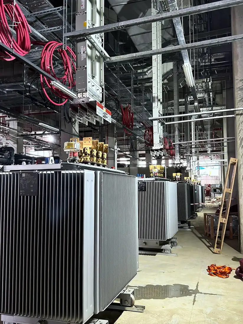
Miratek Elektrik handles cable pulling, termination, grounding connections and the pre-commissioning test plan as a single workflow in medium-voltage contracting and underground network projects across Türkiye. Cable termination, cable pulling, fiber optics and grounding were among our scopes in the BESS electrical works we carried out for Chint Power Systems at the Killik Wind Farm site. On wind farm, BESS and transformer substation projects, we plan termination and testing not as separate jobs but as links in the same quality chain.
Frequently Asked Questions
Which tests should be performed after MV cable termination installation?+
After insulation resistance and outer sheath tests, a 0.1 Hz VLF withstand test should be performed, ideally supplemented with tan delta and partial discharge measurements. This verifies both voltage withstand capability and installation quality.
What voltage and duration are used in a VLF cable test?+
The test is performed at 0.1 Hz; voltage and duration depend on the approach adopted. The IEC 60502-2 and HD 620 approach uses 3U0 (36 kV for a 12/20 kV cable) for at least 15 minutes, while the IEEE 400.2 approach uses tabulated values by voltage class for 30 to 60 minutes. The applicable approach should be defined in the contract in advance.
Why is DC voltage testing no longer preferred for XLPE cables?+
IEEE 400 and most manufacturers do not recommend high-voltage DC testing for XLPE cables, because DC voltage can cause space-charge buildup and may not reveal some defects that would cause problems under AC operation. IEC 60502-2 still lists a 4U0 / 15-minute DC option for newly installed cables, but it should not be used on cables in service, which is why AC-based tests such as VLF are preferred.
Why is partial discharge measurement important?+
It reveals defects that pass the withstand test but will grow in service, and combined with reflectometry (TDR) it shows whether the source is a termination, a joint or the cable body.
Why do cable termination failures appear months later rather than immediately?+
An installation defect causes local field concentration and partial discharge; the discharges gradually erode the insulation, and breakdown only occurs once that process is complete.
Related
- ServiceOverhead and Underground Power Networks
- ServiceMedium Voltage
- ServiceTransformer Substations
- ArticleWind Farm Electrical Works: How Are the MV Collector System, Fiber Optics and Grounding Installed?
- ArticleTransformer Substation Provisional Acceptance in Türkiye: What Does the TEDAŞ Acceptance File Require and What Does the Committee Inspect?