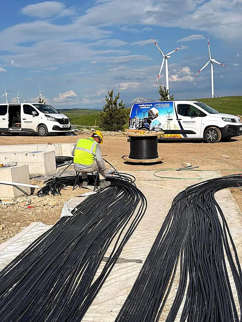
What stages make up the electrical works on a wind farm site?
Electrical works on a wind farm site cover route and trench preparation, turbine foundation grounding, MV cable laying, cable joints and terminations, fiber-optic installation, connection to the substation switchyard, and finally testing and energization. These stages run in lockstep with the turbine erection program: foundation grounding must be finished before the concrete is poured, and cable terminations can only be made once the MV switchgear inside the tower is in place. That is why the electrical works plan has to be built together with the civil works and turbine installation schedules. (In Turkish project documents, a wind farm is called a RES, short for rüzgar enerji santrali.)
In a typical division of scope, the turbine supplier is responsible for the in-turbine electrical equipment and the connections inside the tower, while the electrical contractor delivers the site-wide electrical infrastructure. The turbine supplier's interface documents, meaning grounding connection points, cable entry details and termination types, should be in hand before any site work starts.
On the site layout, the crane hardstands used for turbine erection must not clash with cable routes. Open-trench time should also be kept short, both for worker safety and because trench walls can collapse in heavy rain; wherever possible, excavation, cable laying and backfilling should be completed in a single continuous workflow.
How is the MV collector system between turbines designed and installed?
The MV collector system is usually designed as radial feeders that connect several turbines one after another on the same circuit, installed as underground cable in trenches. Each turbine steps its generator voltage up to medium voltage through its own transformer, and the collector system carries that power, feeder by feeder, to the MV switchgear in the substation. The number of turbines per feeder, conductor cross-sections, voltage drop, losses and short-circuit withstand are the main design parameters.
On wind projects in Türkiye, the collector voltage is most often 34.5 kV (36 kV equipment class), and the MV winding of the main power transformer and the feeder panels in the substation are selected to match. Cable ampacity is calculated from burial depth, spacing between circuits and soil thermal resistivity, with the IEC 60287 series as the common reference. Because the load on a feeder grows as it approaches the substation, stepping up the conductor size along the feeder is a widely used optimization. Ring configurations that tie feeders together at their far ends are possible, but radial layouts remain more common on wind farms because of their lower cost and simpler protection.
During installation, the trench bottom is cleared of rocks and sharp objects, the cables are laid on bedding material, and protective covers and warning tape are placed above them. Cable drums are handled with suitable lifting equipment; pulling tension and bending radius are kept within the manufacturer's limits, and cut ends are sealed immediately against moisture. At road and stream crossings the cables run through protective ducts, and the route is marked on site.
Where and how are MV cable joints and terminations made on a wind farm?
MV cable terminations are made at the MV switchgear inside each turbine tower and at the feeder panels in the substation, while cable joints are made only at intermediate points where a drum length runs out or the route makes one unavoidable. Turbine switchgear usually takes separable T-type (plug-in) connectors, and the termination type must be compatible with the switchgear manufacturer's interface. Because every joint is a potential failure point on the circuit, the number of joints is kept to a minimum.
Joints and terminations are made by crews trained on the specific product, following the manufacturer's installation instructions to the letter. Quality comes down to cable preparation: removing the semiconductive layer to the correct dimension with a clean cut, keeping surfaces free of moisture and dust, and making a solid screen connection. In rain or dust, a sheltered workspace such as a jointing tent is set up, and each joint's position is recorded by GPS coordinates and marked on the ground.
Where the cable screens are grounded, for example at one end or at both ends, is a design decision and must be implemented on site exactly as designed. An incorrect screen connection can cause unwanted circulating currents or hazardous voltages on the screen, shortening cable life and compromising worker safety.
Why should wind turbine grounding and the site grounding grid be treated separately?
Wind turbine grounding and the site grounding grid should be treated separately because they serve different purposes, are built at different times and are often designed by different parties, yet in the end they must operate as one system. Turbine grounding is designed primarily to carry lightning current safely from the blades, nacelle and tower into the ground, with IEC 61400-24 as the reference standard. The site grounding grid, by contrast, limits touch and step voltages during MV faults and holds all turbines at a common potential.
Turbine foundation grounding consists of ring electrodes placed around the foundation plus bonds to the foundation reinforcement. It must be completed and inspected before the concrete pour, because access afterward is practically impossible. The site grid typically links the turbines to each other and to the substation grounding system with bare copper conductor laid along the MV cable trench. This interconnection lowers each turbine's individual grounding resistance and widens the area over which fault current dissipates.
Connections are made by exothermic welding or with approved connectors and photographed for the record before they are buried. Resistance and continuity measurements of the completed system are reported separately; we cover measurement methods and periodic inspection requirements in detail in our grounding measurement guides.
Which topology is used for the fiber-optic network on a wind farm?
A ring topology is the most common choice for a wind farm's fiber-optic network, so that if the cable is damaged at any single point, communication with the turbines continues from the opposite direction. The fiber network links the turbine control systems, the site SCADA, the power plant controller (PPC) and the protection and control system in the substation. Because distances are long, single-mode fiber is generally used.
The fiber cable runs in the same trench as the MV cables but inside a separate protective duct, which adds mechanical protection and makes later cable pulling easier. Fusion splices are made in a splice enclosure or patch panel at each turbine, splice losses are measured, and every fiber is clearly labeled with the turbine it serves. The complete network is handed over with bidirectional OTDR test records.
When sizing the fiber count, account not only for turbine communication but also for the met mast, site security cameras and possible future expansion. Leaving spare fibers is always cheaper than pulling a new cable later.
Which tests are performed before connecting to the wind farm substation?
Before connection to the substation switchyard, MV cables undergo insulation resistance measurement, a VLF withstand test and an outer sheath test; fiber links are verified by OTDR; and the grounding system gets resistance and continuity measurements. Phase identification and phase sequence checks on each feeder confirm that the phases at the turbine end match the panels in the substation. Where the specification calls for it, partial discharge or tan delta measurements are added to the test program.
Test sequence matters as much as the results: insulation resistance is measured before and after high-voltage tests such as VLF to confirm that the test itself has not damaged the cable. When testing with terminations connected to switchgear, equipment such as surge arresters and voltage transformers is disconnected, or the test method approved by the switchgear manufacturer is used.
On the substation side, protection relay settings and secondary injection tests, functional checks of the feeder panels and SCADA signal tests are completed. Energization then proceeds feeder by feeder under a written program, with lockout/tagout procedures, and in line with the acceptance process of the relevant grid operator: TEİAŞ (Turkish Electricity Transmission Corporation) for transmission-connected plants or the regional distribution company for distribution-connected ones. Test reports, as-built route drawings and joint coordinates are handed over to the operations team.
How do difficult terrain and weather affect wind farm electrical works?
Difficult terrain and weather directly determine the schedule, equipment choices and quality risks of wind farm electrical works. Wind farms are often built on exposed ridges and hilltops, on rocky ground and at locations reached by steep access roads. Trenches that require rock excavation slow progress, and in stretches that drum-carrying vehicles cannot reach, crews carry and lay the cable by hand.
Cold weather reduces cable flexibility, so cables are never laid below the manufacturer's minimum installation temperature, and drums are pre-warmed when needed. Rain affects trench stability and jointing work, high winds stop crane operations, and open-field work is restricted on days with storm or lightning risk. Seasonal work windows should therefore be planned together with the turbine erection program, with weather contingency built into the schedule.
Miratek Elektrik delivers wind farm electrical works across Türkiye, including MV cable laying, cable terminations, fiber optics and grounding installation, backed by more than 15 years of experience and 85 km of MV/LV cable lines completed. The BESS electrical works we carry out for Chint Power Systems at the Killik wind farm site in Tokat, covering cable pulling, fiber optics, cable terminations and grounding, have given our crews hands-on experience with the terrain and safety conditions of a wind farm site. Agreeing on a realistic, site-specific work program at the survey and scope definition stage makes every later phase easier.
Frequently Asked Questions
What is an MV collector system on a wind farm?+
It is the on-site network, usually built with underground cables, that carries the turbines' power, already stepped up to medium voltage, feeder by feeder to the substation. It is also called the collection system or collector network.
Why are wind turbines bonded to each other with a grounding conductor?+
To keep all turbines at a common potential, lower the overall grounding resistance and dissipate fault currents safely. The bond is usually made with bare copper conductor laid along the MV cable trench.
Why is the fiber-optic network on a wind farm built as a ring?+
For redundancy. If the cable is damaged at a single point, communication with the turbines continues from the other direction of the ring.
Which tests do wind farm MV cables undergo before energization?+
Insulation resistance measurement, a VLF withstand test, an outer sheath test and phase checks. If the specification requires it, partial discharge or tan delta measurements are added.
Related
- ServiceWind Farm Design
- ServiceOverhead and Underground Power Networks
- ServiceLightning Protection and Grounding
- ArticleWhy Does MV Cable Termination Require Specialist Skills? Common Mistakes and VLF / Tan Delta Testing
- ArticleBESS Electrical Works at the Killik Wind Farm: How Is Battery Energy Storage Commissioned on Site?