Where do civil and electrical works intersect on a BESS site?
Civil and electrical works intersect at four points on a BESS site: container foundations, cable trenches and ducts, the grounding (earthing) grid, and site roads and crane pads. At each of them, the civil crew's work fixes the conditions for the electrical crew's later work, and most mistakes end up under concrete or backfill. Correcting them after the containers arrive costs far more than measuring them before the pour.
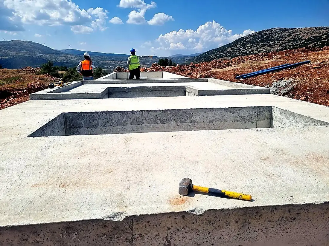
Foundations carry cable entry openings, cast-in ducts, anchor or weld plates and grounding tails. Trenches need a route, cross-section, fall, drainage and cover type defined by electrical needs rather than by convenience. The grounding grid is laid while excavations are open, and its relationship with foundation rebar must be defined in the design. Roads carry container trucks and cranes and are crossed by cables, so every road crossing needs its ducts, plus spares, before the road base goes in.
On BESS projects in Türkiye the battery and PCS supplier is often foreign while the civil and electrical subcontractors are local, so interface drawings pass through several hands and sometimes through translation. The most effective control is a single coordination drawing that overlays civil and electrical layouts, combined with a pre-pour inspection record signed jointly by civil, electrical and EPC representatives before every pour. The record lists duct counts, positions, grounding tail locations and photos. Our article on BESS electrical scope of work covers the wider responsibility split; this one stays with site readiness before delivery.
Why should cable entry openings and anchor positions on container foundations be verified in advance?
Cable entry openings and anchor positions on BESS container foundations must be verified in advance because the cable entries and fixing points in a container's base frame are fixed at the factory and cannot be moved on site. If a foundation opening or anchor is in the wrong place, the fix is core drilling, breaking out concrete, or failing to set the container in its planned orientation. Verification must use the supplier's latest foundation interface drawing. Battery, PCS and transformer container drawings often move on separate revision tracks, so the revision used for each foundation should be written on the pre-pour record.
Start with orientation: door side, HVAC unit position and cable entry side determine the direction from which the trench must approach the foundation. Then measure the number, diameter and coordinates of openings or ducts for DC, LV, signal and grounding relative to the container axes. The bend radius of cast-in duct sweeps must suit the minimum bending radius of the largest cable that will pass through; otherwise the insulation is overstressed during pulling, or the cable will not go through at all.
Top-of-foundation level and flatness must stay within the supplier's tolerances, or the container frame is stressed and doors and gland plates fall out of alignment. A practical method is to build a template from the container base drawing, fix ducts and anchors to it inside the formwork, and survey their positions with a total station before the pour. Unused ducts should be capped, spare ducts labelled, and the method for sealing cable entries against water and rodents agreed before the containers arrive.
How should the DC, LV and signal cable trenches between batteries and PCS units be planned?
DC power, LV power and signal cables should be planned in separate ducts or segregated trench compartments, sized from a frozen cable schedule, with clear separation between them. DC power cables are only part of the picture between batteries and PCS units: LV auxiliary supplies for HVAC, fire detection and lighting, and signal and fiber cables for BMS communication follow the same route. Sizing a trench for power cables alone usually ends with signal cables squeezed on top of them.
Duct and trench fill must leave room for both pulling and heat dissipation. Grouped power cables lose current-carrying capacity, and that derating has to appear in the cable sizing calculation as a grouping factor. Signal cables run in their own duct or in a compartment with a metal divider, and crossings with power cables are made as close to right angles as possible. On long runs, draw pits are placed as pulling and jointing points.
Drainage is the most neglected item. If trenches do not fall towards a draw pit or drain point, rainwater can travel along the cable route into container bases. Covers and ducts at road crossings are rated for vehicle loads; directly buried cables get a sand bed, mechanical protection and warning tape. Every duct and compartment should be labelled at both ends and match the route numbers in the cable schedule. A spare duct left at this stage saves a later excavation for an added sensor or fiber link.
Why should the grounding grid be installed and continuity-tested before the concrete is poured?
The grounding grid should be installed and continuity-tested before the concrete is poured because grounding conductors and joints beneath and inside a foundation become inaccessible once the pour is complete; a broken or weak joint can then only be found and repaired by breaking out. The grid should therefore be completed while the excavation is open, continuity-tested and recorded with photos before the pour is released.
In practice the site grid is laid in bare copper conductor or galvanized steel tape at the design cross-section, with main grid joints made by exothermic welding. Each battery container, PCS and transformer gets a grounding tail of sufficient length at the point shown in the design, protected from concrete and plant traffic. Whether and how foundation rebar is bonded to the grid must be stated explicitly in the design. Mechanical connectors belong only where they will remain accessible.
Before the pour, continuity between each tail and the main grid is measured with a low-resistance ohmmeter and logged against the tail number. Overall grid resistance is usually measured with the fall-of-potential method once the whole grid is complete, and assessed against the project specification and Türkiye's Regulation on Grounding in Electrical Installations (Elektrik Tesislerinde Topraklamalar Yönetmeliği), which applies alongside any international design standard named in the contract. Typical failures are tails crushed or cut by excavators, outlets left on the wrong side, conductors damaged during backfill and joints buried without being recorded. Where the battery yard sits next to an existing substation, the bonding points between the two grids belong on the same record.
What does the electrical team check while the containers are being craned into place?
Before each container is lowered, the electrical team checks that foundation openings are clear and clean and that grounding tails are in place and protected; after it lands, the team confirms orientation, alignment of cable entries with the ducts and access to the grounding connection points. These checks should be part of the lifting plan, because lifting a container that has already been set means another crane day.
Pre-lift checks cover duct caps still in place, no concrete debris or standing water in the openings, and grounding tails bent so they will not be crushed. If an energized MV overhead line or live equipment is nearby, crane boom clearance and, where needed, an outage are agreed with the plant's operations team before the lifting day. Cable crews stay out of the area under the load; the electrical team's work starts once the lift is complete.
Once the container is set, the first task is bonding its frame to the site grounding grid; no cable pulling should start before that bond is in place. Next, the alignment of gland plates with the foundation ducts, any transport damage to the container body and, where the supplier requires it, the state of shock and tilt indicators are recorded. Cable entries are temporarily closed to keep moisture and dust out of the container. Permanent entry sealing follows cable installation, using the material the supplier specifies.
What did the electrical subcontractor's site scope include on the Killik wind farm BESS project?
On the BESS project at the Killik wind farm in Tokat, we worked as the electrical works subcontractor under Chint Power Systems, and our site scope covered six items: DC cable installation and battery module wiring; LV and signal cable runs between the PCS and battery containers; electrical assembly and connections during crane placement of battery and PCS-transformer containers onto concrete foundations; busbar connections; grounding and site cable infrastructure; and testing and commissioning support.
Three of those items, namely the LV and signal cable runs, the electrical assembly during container placement, and grounding and site cable infrastructure, sit directly on the civil-electrical interface this checklist covers. All three progress in the same area and on the same schedule as the civil works. That is why we treat site readiness as the first step of the electrical programme rather than as a civil matter owned by someone else. Our project article describes the wider works.
Miratek Elektrik carries out grounding, site cable infrastructure, MV and LV cabling and testing-commissioning on BESS, solar and wind sites across Türkiye. Over more than 15 years we have completed 85 km of MV/LV cable lines, and our site work runs under an ISO 45001:2018 certified occupational health and safety management system. For EPC contractors and battery suppliers, we can arrange a site survey under our Renewable Energy service to review foundation interface drawings, the trench plan and the grounding design before the containers arrive.
Frequently Asked Questions
Which drawing should cable entry openings on a BESS foundation follow?+
They should follow the latest foundation interface drawing from the battery, PCS or transformer container supplier. Record the revision used on the pre-pour inspection record, and recheck formwork and duct positions whenever that drawing is revised.
When is grounding continuity tested on a BESS site?+
Continuity between each grounding tail and the main grid is measured with a low-resistance ohmmeter before the concrete is poured and logged against the tail number. Overall grid resistance is usually measured with the fall-of-potential method once the full grid is complete.
What is the first electrical task after a container is set on its foundation?+
Bonding the container frame to the site grounding grid. Cable pulling and other connections should not start until that bond is in place.
Who is responsible for BESS site-readiness checks?+
Foundations and trenches usually sit with the civil contractor, grounding and cable infrastructure with the electrical contractor, and coordination with the EPC. The check only works if the pre-pour inspection record is signed jointly by all three.
Related
- ServiceRenewable Energy
- ServiceLightning Protection and Grounding
- ServiceSite Survey and Quantity Takeoff
- ArticleBESS Installation Electrical Scope of Work: How Responsibility Is Split Between the Battery Supplier, the EPC Contractor and the Electrical Contractor
- ArticleBESS Electrical Works at the Killik Wind Farm: How Is Battery Energy Storage Commissioned on Site?